Remote Control Door Lock Circuit Diagram

Infrared Remote Controlled Door Lock Circuit Home Security Wireless Home Security Circuit Projects

Remote Switch Circuit Circuit Diagram Remote Control Light Electronic Circuit Design

The Brilliant Door Access Control System Wiring Diagram With Regard To Your Property Yugteatr Access Control System Access Control Home Theater Wiring

Door Lock Actuator Wiring Diagram Wellread Me And Power Magnetic Door Lock Electrical Wiring Diagram Door Locks

Password Based Door Lock System Using 8051 Microcontroller Door Lock System Alarm Systems For Home Home Security Tips

Adding Power Remote Locks To Amc The Amc Forum Automotive Mechanic Electrical Diagram Automotive Repair

The above tx is an easy rc based two transistor oscillator which might be employed as the tx remote handset for the suggested ir door lock circuit.
Remote control door lock circuit diagram.

Password Based Door Lock System Using 8051 Microcontroller Door Lock System Microcontrollers Circuit Diagram

Ir Remote Control On Off Switch Circuit Envirementalb Com Circuit Remote Control Electrical Circuit Diagram

Control 8 Appliances With Single Remote Circuit Projects Electronic Circuit Projects Circuit

How To Make Remote Control Door Lock At Home Diy Electric Project Remote Control Door Lock Diy Lock Remote Door Lock

Password Based Circuit Breaker Project Circuit Working Circuit Diagram Circuit Breakers

The Brilliant Door Access Control System Wiring Diagram With Regard To Your Property Yugteatr Access Control System Access Control Magnetic Lock

Ir Infrared Remote Control Switch Circuit And Applications Tv Remote Controls Remote Remote Control
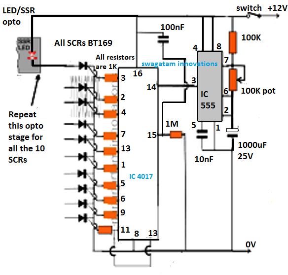
In This Article We Elaborately Learn To Make A 2 4ghz 10 Channel Remote Control Switch Circuit Usin Circuit Projects Electronic Circuit Projects Remote Control

Remote Controlled Smartfan Using At89c2051 Full Electronics Project Electronics Projects Remote Electronics

Pin On Electronica

2 4 Ghz 10 Channel Remote Control Switch Circuit Projects Remote Control Remote

Remote Controlled Fan Dimmer Controller Switch Circuit In 2020 Circuit Projects Electronics Circuit Fan

Instruction Manuals In 2020 Murphy Door Electromagnetic Lock Shop Doors

Access Control Power 8 Access Control Access Control System Control System

Rf Remote Controlled Mobile Robot Based On Pt2272 And Pt2262 Circuit Diagram World Mobile Robot Circuit Diagram Remote

Camera Remote Shutter Release Circuit Basic Circuit Remote Basic

New Wiring Diagram For Garage Lighting Diagram Diagramsample Diagramtemplate Wiringdiagr Garage Door Sensor Automatic Garage Door Opener Garage Door Safety

Bluetooth Controlled Electronic Home Appliances Home Automation Project Home Automation System Home Appliances
Https Encrypted Tbn0 Gstatic Com Images Q Tbn 3aand9gcrpvvkk6rhjo B7n2mcauinxoesiptfz Cu83kmui1irpzddzad Usqp Cau

Here Is The 5 Channel Ir Remote Control System Circuit Diagram Working And Applications This C Electronics Mini Projects Mini Project For Electronics Circuit

Learn To Interface 4x4 Keypad Matrix To Arduino With Keypad Code And Keypad Arduino Connection It Is Used In Security Lock Door Arduino Interfacing Tutorial

How Rfid Works And How To Make An Arduino Based Rfid Door Lock Access Control Control Arduino

Wireless Doorbell For Your Home And Office Electronics Diy Project Wireless Doorbell Electronics Projects Diy Electronics For You

Ir Sensor Circuit And Working With Applications Electronics Circuit Electronics Basics Circuit Diagram

Fingerprint Door Unlock System Arduino Keeping You Safe Arduino Arduino Projects Projects
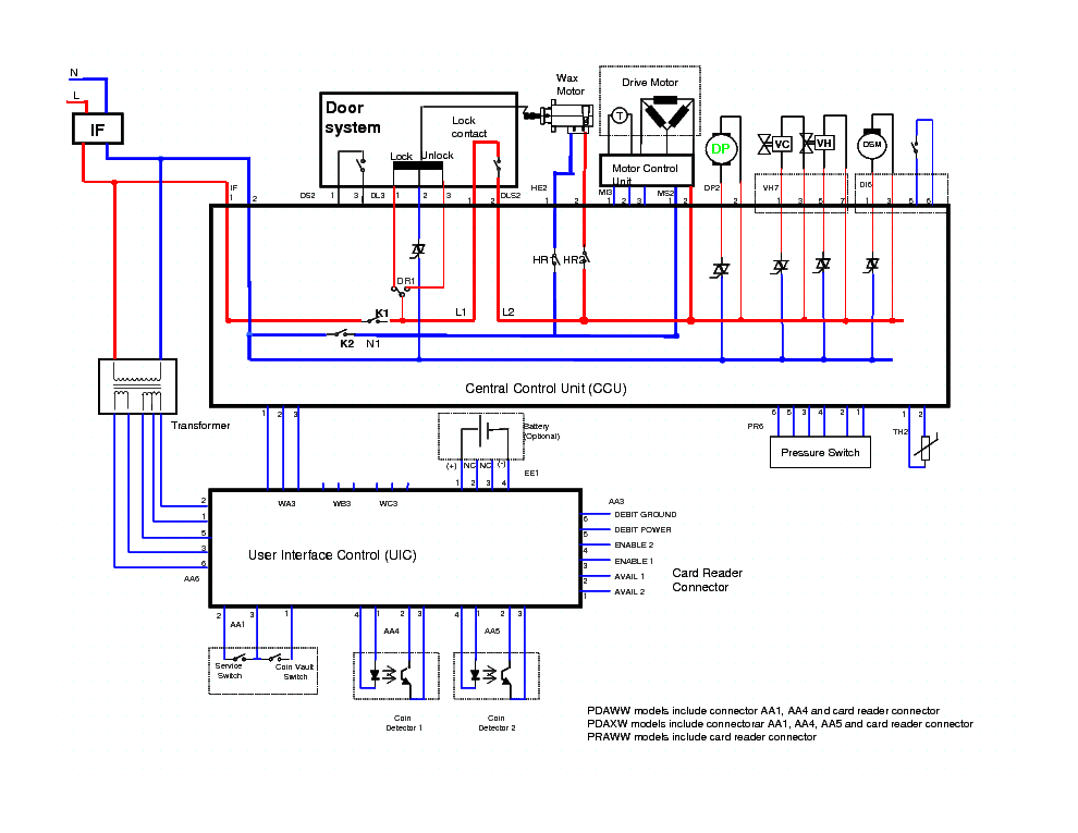
Wiring Diagram Of Washing Machine Timer Washing Machine Motor Washing Machine And Dryer Washing Machine

Ir Remote Controlled Triac Ac Light Dimmer Circuit Diagram Circuit Diagram Circuit Electronics Circuit

Single Pulse Push Button Door Locks Automotive Electrical Relay Alternator

Pin On Arduino Projects

Smart Receptionist With Smartlock System Software Projects System Office Door

Best Relay Wiring Diagram 5 Pin Wiring Electrical Circuit Diagram Electrical Diagram Trailer Wiring Diagram

Ir Infrared Remote Control Switch Circuit Remote Remote Control Electronics Projects
Electronics Circuits For Projects Ece Diagrama Electronico Electronica Circuito

Https Encrypted Tbn0 Gstatic Com Images Q Tbn 3aand9gctl2 3ose78yfgs7fuldjycl3m Dmbkxw Qkq Usqp Cau

Ir Remote Controlled Triac Ac Light Dimmer Circuit Diagram Circuit Diagram Circuit Electronics Circuit

Pin On Automotive

9 Burglar Alarm Circuit Ideas Electronics Projects Circuits In 2020 Electronic Circuit Projects Burglar Alarm Electronics Projects

Unusual Freightliner Power Window Wiring Diagram Images Beautiful And Motor Trailer Wiring Diagram Windows Automotive Electrical

Pic Microcontroller Based Electronic Lock Circuit Diagram

Circuit For Controlling Audio Volume And Tone Using Microcontroller Microcontrollers Remote Control Volume

11 Good Wiring Diagram For 3 Way Switch With Multiple Lights Ideas Electrical Wiring Diagram Remote Car Starter Diagram

Best Relay Wiring Diagram 5 Pin Bosch Endearing Enchanting Blurts Me Electrical Circuit Diagram Electrical Diagram Trailer Wiring Diagram

Multi Way Switch Circuit Diagram Circuit Diagram Electronic Gift Ideas Circuit
Https Encrypted Tbn0 Gstatic Com Images Q Tbn 3aand9gcqczgft8nnwmpemsldl7083sjxhbaikhnimle0hjvud8qimaddu Usqp Cau
Source : pinterest.com
